


Jeep Front Suspension Diagram
If you're planning a suspension upgrade or diagnosing steering issues, understanding the Jeep front suspension diagram is essential.
This visual map reveals how control arms, track bars, and linkages interact and why geometry matters when you're pushing your rig off-road.
So, whether you're wrenching on a TJ, JK, JL, XJ, or Gladiator, this guide covers what every serious builder should know before lifting, linking, or fabricating new parts.
What this article covers:
- What Is a Jeep Front Suspension Diagram?
- Key Components Shown in the Diagram
- How to Read the Diagram and Use the Legend
What Is a Jeep Front Suspension Diagram?
A Jeep front suspension diagram is a technical illustration (usually exploded or labeled) that shows how the suspension and steering components mount and move together.
It helps identify parts by number or name and is often used in factory service manuals, aftermarket install guides, and fabrication setups.
For off-road Jeep platforms like the TJ, this diagram gives you a top-down understanding of how the five-link, coil-sprung front axle system works. Every control arm, coil spring, shock, and steering link is positioned for a reason. When one angle is off or a bushing fails, the whole system suffers.
A clear diagram helps avoid guesswork, especially when upgrading to long arms, high-clearance steering, or heavy-duty track bars.

Key Components Shown in the Diagram
Below are the core parts you'll find, along with how they operate and where they're likely to fail under trial abuse.
Upper and Lower Control Arms
Your Jeep's front axle is located by two upper and two lower control arms. These pivot from frame brackets to axle brackets, allowing the axle to move up and down while staying centered front-to-back.
Lower arms control caster angle and absorb most of the stress during acceleration and braking. Upper arms fine-tune pinion angle and manage articulation geometry.
Stock arms use rubber bushings that wear quickly under flex. CavFab's steering and suspension collection includes heavy-duty control arms made from CNC-machined solid steel with adjustable ends for fine-tuned geometry.
Coil Springs and Shock Absorbers
The coil springs support the Jeep's weight and control ride height, while the shocks dampen movement and keep tires planted.
In a diagram, coils are typically shown seated on lower spring perches atop the axle and compressed beneath the bump stop towers.
When you lift a Jeep 2.5" or more, spring rate and shock length must be re-matched to avoid coil binding or topping out. Builders often install Jeep Wrangler TJ parts to preserve wheel travel and ride control.

Track Bar, Pitman Arm, and Drag Link (Steering Linkage)
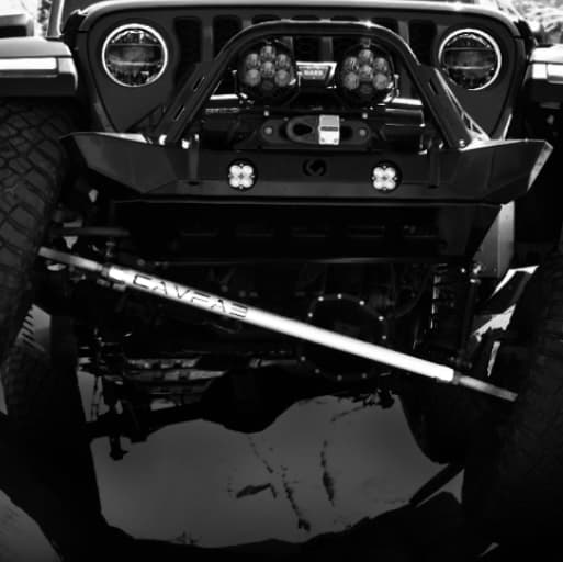
The front track bar keeps the axle centered side-to-side and mirrors the arc of the drag link to prevent bump steer.
The Pitman arm drops from the steering box and connects to the drag link, which transfers motion to the passenger-side knuckle. If these components are mismatched (especially after a lift), you'll feel vague steering, wandering, or even death wobble.
Our Over the Axle (OTA) Track Bar System eliminates this issue by improving track bar geometry and clearance.
Sway Bar (Stabilizer Bar) and Links
Mounted across the frame, the front sway bar (also called a stabilizer bar) resists body roll during cornering. It connects to the axle via sway bar links.
On the diagram, it's typically shown as a curved rod above or forward of the axle centerline.
While many off-roaders disconnect the sway bar for trail runs, it's critical for highway safety and load balance. Upgraded quick-disconnect links let you tune flex without losing on-road stability.
Ball Joints and Steering Knuckles
At the far ends of your steering system, the ball joints let your steering knuckles pivot for turning while supporting vertical load.
These are mounted inside the C ends of the axle and shown on diagrams as spherical or jointed pivots at the top and bottom of each knuckle.
Ball joints wear out under larger tires and repeated impacts. Loose or seized ball joints lead to steering slop, uneven tire wear, and suspension misalignment. Replacing them with high-angle, serviceable ball joints restores trail confidence and reduces death wobble risk.

How to Read the Diagram and Use the Legend
Most Jeep front suspension diagrams are either exploded-view illustrations or component maps with callouts.
Each part is assigned a number that corresponds to a legend or part list, which often includes factory torque specs and part names.
Look for these cues to navigate the diagram:
- Control arms are shown diagonally linking the frame and axle
- The track bar runs side-to-side near or above the axle
- Pitman arm connects to the steering box at a steep angle
- Tie rod and drag link run laterally and diagonally, respectively
- Sway bar curves around the front and may be ghosted out in exploded views
Use the diagram as a baseline to plan upgrades. If your new steering system doesn't follow the same arc as the factory geometry, you'll need to correct it with adjustable track bars, drop brackets, or a matched drag link and Pitman arm setup.
Conclusion
A Jeep front suspension diagram is your map to smarter upgrades and stronger steering. It shows you where each component mounts, how motion transfers through the system, and which parts demand reinforcement first.
At CavFab, every part is engineered for geometry, strength, and trail survivability. Our Jeep parts are built from USA-sourced steel, backed by a lifetime warranty, and trusted by builders across the country.
Ready to learn more about front-end setups? Check out these articles: